
Post-Project Disaster: A production machine needed chilled water, but the safety valve (Pressure Relief Valve – PRV) kept popping.
The $15,000 Pump Nobody Needed
How a $0 Baseline & Expansion Tank Adjustment Resolved a Critical Plant Deadlock
The Post-Commissioning Crisis
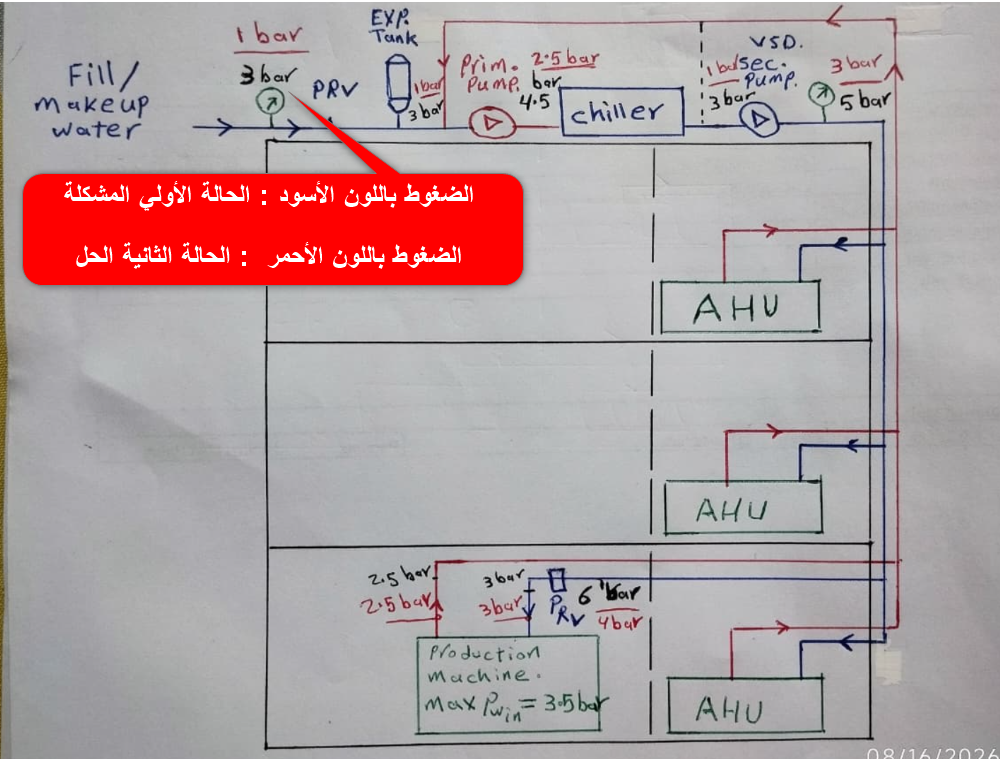
Immediately following project handover, a primary production machine failed to operate. The machine required chilled water for cooling but kept tripping its internal safety switch. The incoming line pressure was 6.0 bar, whereas the machine had a strict upper safety cutoff threshold of 3.5 bar.
To protect the equipment, a Pressure Reducing Valve (PRV) was installed to step down the machine inlet pressure to 3.0 bar. The result: Water circulation stopped entirely.
Case 1: The Hydraulic Trap [Black Values]
- Supply Inlet: 3.0 bar (throttled by PRV)
- Roof Pump Suction: 3.0 bar
- Static Elevation Head: +1.0 bar (10m vertical riser)
- Machine Exit Backpressure: 4.0 bar (3.0 + 1.0)
- Differential Pressure (ΔP): -1.0 bar
- Outcome: Flow stalled. Water trapped in machine.
Case 2: The $0 Engineering Fix [Red Values]
- Expansion Tank Baseline: Reset to 1.0 bar
- Supply Inlet: 3.0 bar (Safe < 3.5 bar limit)
- Roof Suction Baseline: Reduced to ~0.8–1.0 bar
- Machine Exit Backpressure: Dropped to < 2.0 bar
- Differential Pressure (ΔP): +1.0 to +1.2 bar
- Outcome: Instant, active chilled water circulation.
The $15,000 Proposed Mistake
The on-site field recommendation was to treat the symptom by adding capital equipment: purchasing an external booster pump, installing a Variable Frequency Drive (VFD), and integrating a new control loop. This proposed fix carried an estimated equipment cost exceeding $15,000, substantial downtime, and created a severe physical footprint constraint due to zero available space in the plant room.
System Metrics Comparison
| Hydraulic Parameter | Case 1: Initial Setup [Black] | Case 2: CED Optimized [Red] |
|---|---|---|
| PRV Setpoint (Machine Inlet) | 3.0 bar | 3.0 bar |
| Expansion Tank Pre-charge | 3.0 bar (Baseline) | 1.0 bar (Re-engineered) |
| Return Header Backpressure | 4.0 bar | 1.8 – 2.0 bar |
| Driving Gradient (ΔP) | -1.0 bar (Deadlock) | +1.0 to +1.2 bar (Flowing) |
| Capital Expenditure (CAPEX) | $15,000+ (Proposed Pump + VFD) | $0.00 |
Never treat a hydraulic balance issue with a hardware purchase order. When circulation stalls after valve installation, audit the system expansion pre-charge, static head, and differential pressure gradients before adding horsepower.
