
when covering condenser with large plastic bag Is the solution
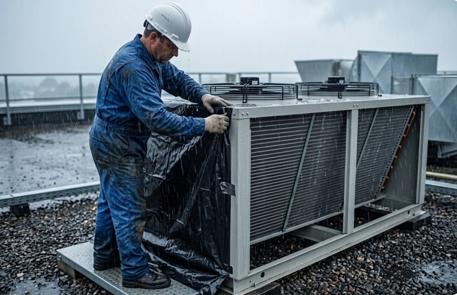
When Covering an Air-Cooled Condenser with a Plastic Bag is the Real Engineering Solution
● The 4:00 AM Crisis in Sub-Zero Rain
At 4:00 AM on a freezing, rain-swept winter night, the duty engineer at a major industrial facility was awakened by an urgent call from the shift technician. A 50 TR direct expansion (DX) air-cooled air conditioning unit operating on R-134a had locked out on its Low Refrigerant Pressure alarm. The technician attempted multiple manual resets, but each time the compressor engaged, the suction gauge plunged immediately into vacuum levels, tripping the Low Pressure Switch (LPS).
The unit served the facility’s central electrical substation and uninterruptible power supply (UPS) room. In industrial infrastructure, electrical switchgear, transformers, and battery banks produce massive sensible heat loads regardless of outdoor weather. Without active, uninterrupted cooling, room temperatures quickly escalate, creating severe thermal runaway risks that can trip main switchgear and shut down an entire strategic production plant.
Within five minutes of partially covering the coil face, the system pressures normalized, the low-pressure trip cleared, and steady cooling was restored to the substation through the morning.
● Understanding the Low-Ambient Cooling Paradox
A common misconception is questioning why an air conditioning unit needs to run when the outdoor ambient is near freezing. While comfort cooling in residential buildings is turned off in winter, precision environments (substations, data centers, server rooms) carry an almost entirely internal, constant heat load.
When standard comfort-cooling DX equipment is deployed in year-round critical applications without dedicated low-ambient design packages, a severe thermodynamic imbalance occurs: the outdoor heat rejection capacity becomes excessively oversized relative to the operating load.
● The Thermodynamic Root Cause: Head Pressure Collapse
Under normal summer design conditions (e.g., 35°C ambient), the condenser rejects heat to warm air, maintaining condensing temperatures around 45°C to 50°C (11.6 bar to 13.2 bar for R-134a).
During a cold winter rainstorm, two aggressive heat-transfer mechanisms take place simultaneously:
- Sensible Overcooling: Cold outdoor air passing through the large finned surface removes heat much faster than the compressor can deliver it into the coil.
- Latent Evaporative Overcooling: Rainwater continuously wets the aluminum fins. The high-velocity airflow from full-speed fans causes this water film to evaporate rapidly, converting the dry condenser into an unintended, highly efficient evaporative condenser.
This combination causes the saturated condensing temperature and pressure (Pcond) to collapse drastically—often dropping below 15°C (4.9 bar).
● Why the TXV Fails in Winter and Drives Suction Pressure Down
The direct casualty of collapsed head pressure is the Thermostatic Expansion Valve (TXV). A TXV is not a positive-displacement pump; it is a variable-area metering orifice whose mass flow rate (ṁref) is governed by the classic orifice flow equation:
• Cd = Discharge coefficient of the valve orifice.
• Aport = Valve opening area modulated by the sensing bulb.
• ρliquid = Density of the entering liquid refrigerant.
• ΔP = Available pressure differential across the valve (Phigh - Plow).
Under normal summer conditions, an R-134a system operates with a high-side pressure of approximately 11.6 bar and an evaporating pressure of 3.5 bar, delivering an available driving differential (ΔP) of around 8.1 bar (117 psi).
When winter rain collapses the head pressure down to 4.9 bar, the available ΔP drops below 2.5 bar (36 psi)—a loss of over 70% in driving force.
Even though the warm sensing bulb drives the TXV wide open (Aport = Amax), the missing hydraulic pressure differential prevents the valve from feeding the required mass of liquid into the evaporator.
● The Suction Pressure Collapse Cascade
Once the expansion valve is starved of refrigerant, a rapid sequence occurs:
- Coil Starvation: The small amount of entering liquid evaporates almost instantly in the first few distributor circuits rather than traveling through the full coil.
- Excessive Superheat: The remaining dry evaporator surface merely heats the vapor, resulting in extremely high superheat (>20 K) and minimal actual cooling.
- Compressor Evacuation: The compressor continues pumping vapor out of the low side at a constant displacement rate. Because incoming mass flow cannot keep up, the compressor quickly evacuates the evaporator tubes.
- Low Pressure Trip: Suction pressure drops below the Low Pressure Switch cut-out threshold (typically 2.0 to 2.2 bar for R-134a), locking out the circuit.
● Why the Plastic Bag Restores Equilibrium
Covering part of the condenser coil face acts as a physical airflow damper. By cutting off air velocity across a portion of the finned area, the overall thermal conductance product (UA) of the heat exchanger is drastically reduced.
With heat rejection restricted, hot discharge gas accumulates thermal energy inside the tubes, forcing saturated condensing pressure back up to safe operating levels (10.0 to 11.5 bar).
Restoring high-side pressure immediately re-establishes the necessary ΔP across the TXV. The valve can again meter design mass flow into the distributor, flooding the evaporator coil and elevating suction pressure safely above the low-pressure cut-out threshold.
● Permanent Low-Ambient Engineering Solutions
While a plastic sheet or baffle is a proven emergency field fix, critical year-round DX systems should always be designed or retrofitted with engineered low-ambient controls:
1. Fan Speed Control (VFD / EC Inverter)
Modulates outdoor fan RPM proportionally based on liquid line pressure or condensing saturation temperature to hold head pressure steady regardless of cold ambient drops.
2. Multi-Fan Cycling Stages
In multi-fan condensing units, staged pressure controllers cycle outer fans offline as discharge pressure decreases, reducing active heat transfer surface area.
3. Head Pressure Regulating Valves (ORI / ORD / KVR)
Mechanical flooding valves that hold liquid refrigerant inside the lower condenser tubes during extreme winter conditions, reducing active condensing area while bypassing hot gas into the liquid receiver.
Interactive Thermodynamic Simulation on CED
Use our live R-134a P-h Diagram & Low-Head Analyzer on the CED platform to interactively simulate all three operational states (Normal Summer, Winter Low-Head Trip, and Field Plastic Bag Correction).
