
Chilled water Buffer tank sizing
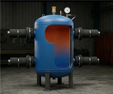
The 4-Pipe Buffer Tank: The "Heart" of Your Cooling System
If you are running a chiller, you need a buffer tank. Think of it as a shock absorber and a battery for your chilled water system.
What does it actually do?
A 4-pipe buffer tank does two big jobs at once:
Hydraulic Separation (The "Shock Absorber"): It lets the Chiller and the Building "breathe" independently. The chiller pump can push exactly what the chiller needs, while the building pump pulls exactly what the rooms need. They don’t fight each other.
Thermal Mass (The "Battery"): Chillers hate turning on and off every 5 minutes (we call this short-cycling). The tank adds a large volume of cold water so the chiller can run in long, steady, efficient cycles.
The "Rule of Thumb" vs. Reality
Most people use a simple guess to size their tanks:
The Guess: 3 to 6 gallons for every "Ton" of cooling.
The Problem: This guess often fails if your building has a very low load at night or if your chiller is high-tech and modulates.
Why use our CED Optimizer? Our calculator doesn't just guess. It uses the "Protection Logic" found in professional engineering standards (like ASHRAE and Idronics). We look at:
Compressor Health: Ensuring the water volume is large enough to meet the chiller's minimum run-time.
Thermal Stratification: Designing for the "Cold Bottom / Warm Top" physics that keeps your system efficient.
Precision Sizing: Calculating the exact Liters/m³ you need, so you don't waste money on a tank that's too big, or risk equipment failure with a tank that's too small.
The Bottom Line
A 4-pipe buffer tank is the cheapest insurance policy you can buy for your chiller. It prevents breakdowns, saves energy, and keeps your building temperature steady.
Don't guess your system’s health. Use our CED Optimizer to get the exact engineering spec for your project.
CED- Critical Engineering Design | BUFFER TANK SIZER & OPTIMIZER
Specify cooling requirements for process equipment served by the tank (e.g., process machines, AHUs).
Chiller Supply assumes 10°C offset from Load if blank. Enter specific data if chiller is pre-selected.
Minimum run time ensures oil return and prevents motor burnout. Minimum part load is the lowest stable chiller stage before shutting off.
Define a full repeating system cycle. This analysis ensures the tank's thermal mass can bridge peak load spikes while allowing the chiller to recover during lower-demand periods.
Hydronic Buffer Tank Sizing Report
CED Engineering | Beginner's Guide to Tank Sizing
What it is: A simple text box to name your project.
How to use it: Type in the name of the client or the specific building (e.g., "Main Pharma Cleanroom"). Whatever you type here automatically prints at the top of your final PDF report so you don't mix up your engineering files.
What it is: This is the Demand Side. It represents the actual machines, air handling units (AHUs), or rooms that need to be cooled.
- Load Flow Rate: How much water needs to circulate through the building (choose GPM, L/s, or m³/hr).
- Load Supply T: The temperature of the cold water leaving the tank and going to the building.
- Load Return T: The temperature of the warm water coming back from the building.
What it is: This is the Supply Side. It represents the Chiller itself (the machine making the cold water).
How to use it: You can usually leave this blank! By default, the software assumes the chiller makes water slightly colder than what the building needs. If you already bought a specific chiller and know its exact temperatures, enter them here.
What it is: Chillers are massive, expensive machines. If you turn them on and off too fast (called "short-cycling"), the motors burn out. We must protect them.
- Min. Run Time (min): Once the chiller turns on, it must run for this many minutes to ensure proper oil return to the compressor.
- Min. Part Load (%): This is the lowest speed the chiller can idle at before it shuts itself off completely.
What it is: Your building doesn't need 100% cooling 24 hours a day. This section maps out the "daily routine" of your cooling needs.
- Row 1: Type
100for Load % and1for Duration. (The factory runs at maximum heat for 1 hour). - Row 2: Type
50for Load % and1for Duration. (The factory slows down to half-capacity for the next hour).
Once you click calculate, the tool generates your system specs:
- Rec. Chiller Size (TR): The recommended horsepower (Tons of Refrigeration) of the chiller you should buy.
- Header Pipe Size: How thick the main steel pipes need to be to carry this much water without causing too much pressure.
- Calculated Buffer Volume: The most important number. This is the exact size of the steel tank you need to buy to act as your water battery.
- t recharge (Min): If your tank is completely drained during a peak spike, this is exactly how many minutes the chiller must run at full speed—with the building machinery turned off—to fill the battery back up with cold water.
Let's say the calculator recommends a 65.6 TR chiller, but you only have a 60 TR chiller in the warehouse. Type "60" into the Manual Chiller Correction box. The software will instantly recalculate and tell you how much bigger your tank needs to be to make up for the smaller chiller!
Once finished, click Print Technical Report to generate a clean, one-page PDF that you can hand directly to a client or supplier.
📚 Deep Dive: Engineering Resources & Further Reading
Want to master the science behind the CED Optimizer? We’ve curated the top industry standards and peer-reviewed research used to develop our calculation engine.
Core Industry Standards
ASHRAE: Design Guide for Cool Thermal Storage (2nd Edition) The definitive global reference for chilled water systems. This guide provides the foundational physics for temperature stratification and "peak shaving" using thermal mass.
Caleffi Idronics #17: Thermal Storage in Hydronic Systems A must-read for any hydronic professional. It explains the "Minimum Run Time" logic we use to protect chiller compressors from the mechanical stress of short-cycling.
Peer-Reviewed Research
Sizing of the Buffer Tank in Chilled Water Systems (Cervera-Vázquez et al.) This study proves the direct link between tank volume and the Seasonal Energy Efficiency Ratio (SEER). It validates why "guessing" your tank size leads to higher electricity bills.
Thermal-Hydraulic Separators Unveiled (Piller & Toneatti) High-level research into fluid dynamics. It explains why maintaining low vertical velocity inside a 4-pipe tank is the only way to achieve true hydraulic independence between your primary and secondary loops.
Practical Design Guides
AMTROL: CWBT Series Engineering Manual A practical look at the physical hardware. This manual covers internal baffle design and anti-short cycle protection for commercial-grade installations.
Technical Glossary for Students
Hydraulic Separation: The process of uncoupling the chiller pump from the building pump so they don’t interfere with each other's flow rates.
Thermal Inertia: The ability of the water volume to resist rapid temperature changes, giving the chiller's brain time to react efficiently.
Stratification: The "layering" effect where cold water stays at the bottom (ready for use) and warm water stays at the top (waiting to be cooled)