
Airlock Pressure Regimes: A Technical Guide to Bubble, Sink, and Cascade Design
Airlock Pressure Regimes
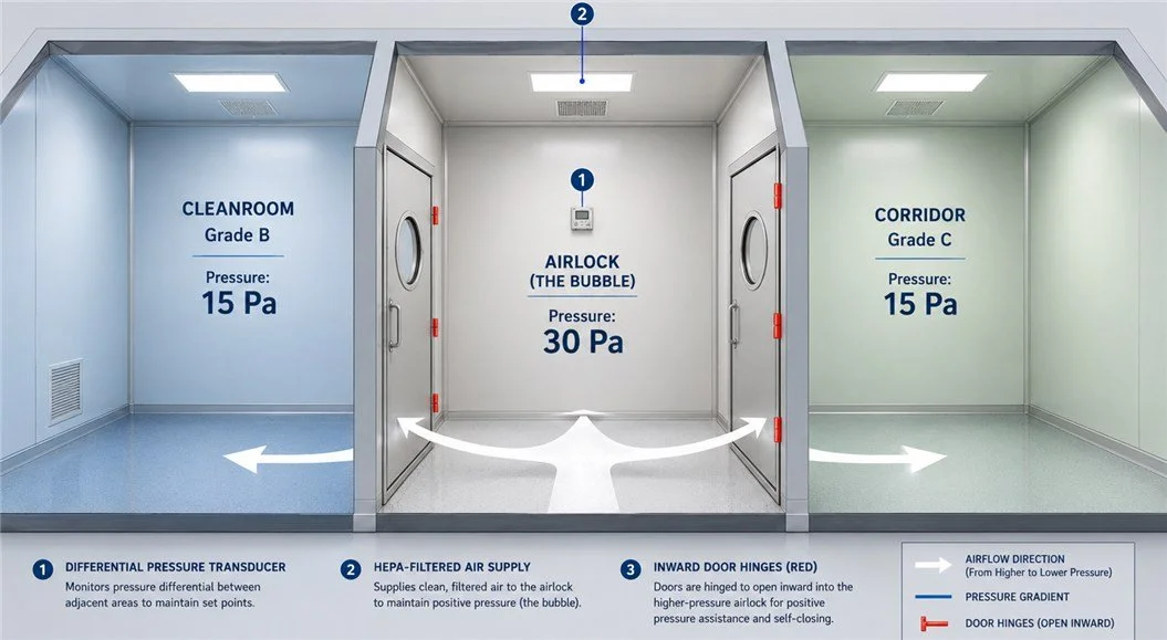
A Technical Guide to Bubble, Sink, and Cascade Design
In critical environments, airlocks serve as the physical and aerodynamic barrier between cleanroom grades. Choosing the correct pressure regime is a mechanical necessity dictated by whether you are protecting the product, the personnel, or the adjacent corridors. Standard GMP practice dictates that doors should open into the higher pressure room to maintain seal integrity.
1. Comparative Matrix
| Type | Pressure Logic | Primary Use Case |
|---|---|---|
| Bubble | P_Airlock > P_Adjacent | Sterile defense (Injectables, Sterile Fill). |
| Sink | P_Airlock < P_Adjacent | Potent compound containment (Hazardous APIs). |
| Cascade | P1 > P_Airlock > P2 | Directional airflow between different Cleanroom Grades. |
2. Interactive Design Simulator
Grade B
Grade B
Grade C
• Door Swing: Hinges are fixed to open into the higher pressure room to ensure seal integrity via pressure-assisted closure.
• Transit SOP: Staff transit must not exceed 3–5 seconds (Maximum allowable duration for door opening).
• Recovery: System is validated to restore ΔP setpoints within 15–30 seconds of door closure.
3. Regulatory Audit Checklist
| Standard | Target ΔP | Audit Focus |
|---|---|---|
| WHO TRS 961 | 15 Pa recommended | Prevents flow reversal due to turbulence. Evaluates recovery alarms. |
| EU GMP Annex 1 | 10–15 Pa minimum | Strict continuous monitoring required between sterile grades. |
| ISO 14644-4 | 5–20 Pa range | Calculates required air volumes to compensate for structural leakage. |
From Theory to Calculation
Mastering the pressure regime is only the first step. To ensure your HVAC system is perfectly sized to maintain these differentials, you must calculate the precise air leakage through your specific door clearances. Use our interactive ASHRAE-standard tool to derive the required Volumetric Flow Rate (CFM/Lps) for your design.