
Cleanroom Manual Washing Layout – Where Should the Ultimate "Pressure Sink" Sit?
When designing a GMP-compliant manual washing suite, HVAC and MEP engineers frequently debate a critical question: Which room should be the absolute lowest pressure point (the ultimate sink)—the Dirty Staging area or the Washing room? 🤔
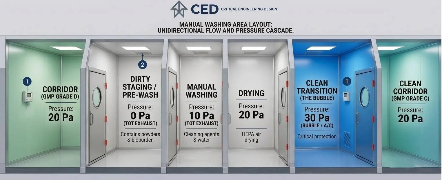
Let’s look at the engineering logic behind this design choice, as illustrated in our technical layout.
💨 The Pressure Profile Challenge
In a standard unidirectional flow setup, the air cascade between the entry corridor, the dirty staging area, and the active wash zone is carefully balanced:
Corridor (20 Pa) $\rightarrow$ Dirty Staging (0 Pa / Absolute Sink) $\leftarrow$ Manual Washing (10 Pa)
⚖️ The Core Debate: Dirty Staging vs. Washing Room
When mapping out containment boundaries, engineers typically weigh two distinct design strategies:
🟢 Option A: Making the Dirty Staging Room the Ultimate Sink (0 Pa)
This is the optimal strategy executed in our infographic layout.
How it works: The Dirty Staging area is set to 0 Pa (Total Exhaust), while the adjacent Washing Room operates at 10 Pa and the entry Corridor at 20 Pa.
Why it wins on Contamination Control: Dirty Staging is where raw, soiled components arrive straight from production. Unboxing, sorting, and handling these components liberates dry dust, bioburden, and raw particulates. By making this room a Sink Airlock (0 Pa), air rushes into it from both the corridor and the washing room.
The Result: Particulates are completely trapped at the frontline. 🛡️ They cannot escape back into the clean corridor or migrate further down the process line.
⚠️ Option B: Making the Washing Room the Ultimate Sink (0 Pa)
An alternative approach sometimes proposed by engineers focused heavily on vapor containment.
How it works: The Washing room is set to 0 Pa, and Dirty Staging is set to 10 Pa.
The Argument for it: The washing area handles hot water, chemical agents, and high humidity, creating heavy aerosols and vapors. The goal here is to ensure steam is sucked out instantly. 🧼
The Structural Flaw: If the Washing room is 0 Pa and Dirty Staging is 10 Pa, air flows from Dirty Staging into the Washing room. While this keeps dust out of the corridor, it risks pulling dry dust and airborne bioburden straight into the wet washing environment, potentially contaminating the washing water and clean surfaces. ❌
🚀 Why This Layout is the Optimal Choice
Our finalized design selects Option A based on two robust validation principles:
Cascading Vapor Control: By keeping the Washing room at 10 Pa, it remains significantly lower than the Drying room (20 Pa) and the Corridor (20 Pa). Moisture and chemical vapors are still perfectly contained—they are simply drawn safely backward toward the 0 Pa Dirty Staging room's total exhaust system. 🔄
Particulate Segregation: This profile respects the rule of physics that dry, airborne particulates (found in Dirty Staging) are far more volatile and harder to control than localized humidity. Localized humidity can be easily managed by a dedicated moisture canopy over the sinks, whereas protecting the corridor from bioburden must always remain the highest GMP priority. 🎯
💬 Join the Discussion
🧠 Engineering Challenge for Students
Look closely at the door swings in the infographic between the Corridor (20 Pa) and the Dirty Staging room (0 Pa). If we reversed the pressure roles and made Dirty Staging 20 Pa and the Corridor 0 Pa, which way would the door have to swing to maintain a proper pressure seal? Let us know your answer in the comments below! 👇